Examples

Five solved studies you can open in Inventor

Each example ships solved, with a guided tour through the real windows. Open it from Explore LaminaroCFD › Examples inside the add-in, or download it here.

Wind on a silo

The wind load on a free-standing silo on open ground, the case EN 1991-1-4 §7.9 covers with a force coefficient. Laminaro builds the air around the part and the log-law wind over the terrain.

Set-up

Part
Ø3 × 6 m silo standing on the ground
Wind
EN 1991-1-4 log-law profile, terrain category II (z0 = 0.05 m); 22.74 m/s at the reference height
Fluid
Air at 20 °C
Out
Drag, lift, Cd, pressure on the walls, the wake, report and video

Result

Drag2 044 N ± 0.1 %
Cd0.365 ± 0.1 %
Lift1 274 N
Checked against: the reference case silo on open ground: cf 0.354 against 0.350 from EN 1991-1-4 §7.9, +1.1 %. The code's cf uses the wind pressure at the top of the silo; the mean force in a log-law wind is about 0.70 of that, so the fair reference is cf0·ψλ·0.70. Laminaro's Cd is the real mean force, which is why it sits below a code cf taken at face value.
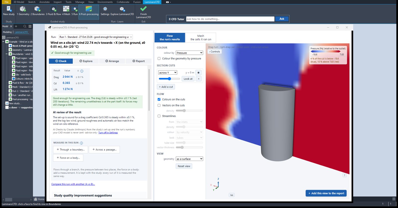
The silo example in Laminaro's post-processing window: drag 2 044 N, Cd 0.365, lift 1 274 N, and the pressure on a section cut.
6 Post-processing › Check: the result, its ±, the verdict and the AI review.
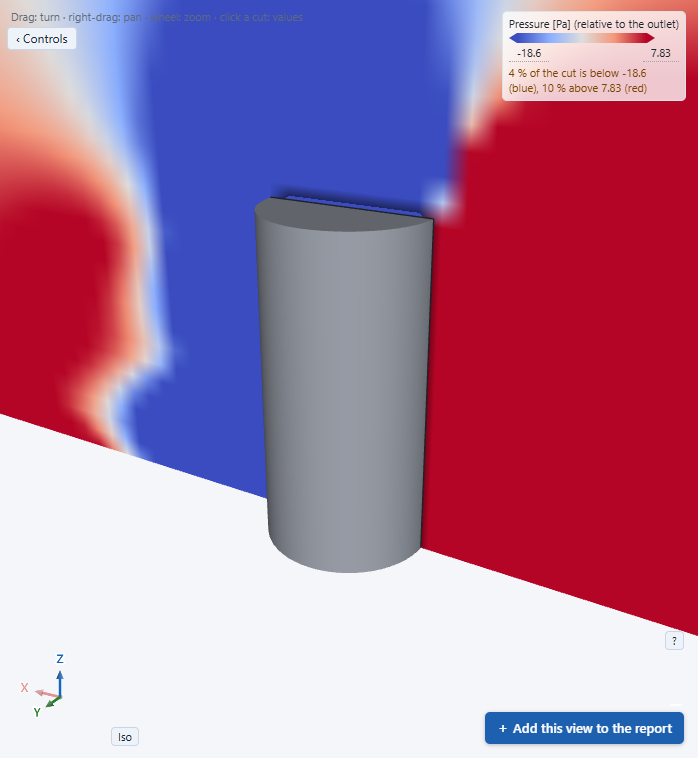
Pressure on a section cut through the silo: high on the windward side, suction in the wake.
Explore: pressure relative to the outlet on a cut through the silo.

Pipe with a sudden expansion

Air through a pipe that steps from Ø50 to Ø100 mm. The textbook case for a loss coefficient, with four measurements along the pipe.

Set-up

Part
Ø50 → Ø100 mm, 1.2 m of pipe
Flow
Air at 20 °C, 10 m/s at the inlet
Model
k-ω SST, chosen from Re 3.3·10⁴
Measured
Inlet, outlet, before and after the step

Result

Pressure drop45.64 Pa ± <0.1 %
K0.758
Flow19.51 l/s
Checked against: Borda–Carnot. The loss at the step alone is K = (1 − (d/D)²)² = 0.5625; the reference case for this step gives 0.5594, −0.5 %. The example's K of 0.758 is from inlet to outlet, so it holds the pipe friction as well as the step.
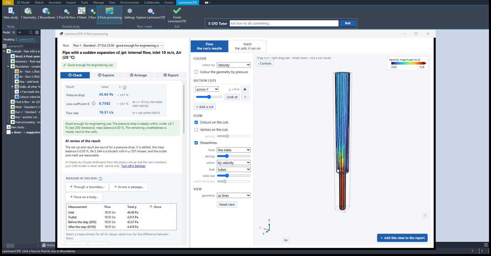
The pipe-expansion example in Laminaro: pressure drop 45.64 Pa, loss coefficient 0.7582, streamlines coloured by velocity, and the four measurements.
Check: the pressure drop, K, the flow rate, and the measurements before and after the step.

Water through a pipe bend

A 90° bend in a Ø50 mm water pipe. For a liquid with one inlet and one outlet, Laminaro leads with the numbers a valve or fitting datasheet gives: the flow coefficients Kv and Cv.

Set-up

Part
Ø50 mm pipe, 90° bend with R 75 mm (R/D 1.5), 5 D before and 10 D after the bend
Flow
Water at 20 °C, 2 m/s (14.1 m³/h)
Mesh
Standard, 515 k cells, converged at 315 iterations

Result

Pressure drop872 Pa
Kv151 m³/h
Cv174
K0.437
Checked against: the hand estimate of Kv, about 150 for this pipe. The K of 0.437 is for the whole pipe: about 0.30 is straight-pipe friction and about 0.14 the bend. The bend's own loss is in the reference suite: K 0.168–0.176 on three meshes against 0.17–0.21 in Idelchik's diagram 6-1 (see Verification).
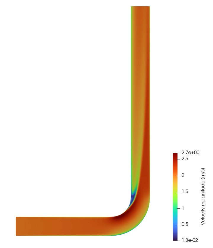
Velocity on a section through the pipe bend: the flow speeds up on the inside of the bend and separates just after it.
Velocity on a cut through the bend: the fast inner side and the slow zone just after it.
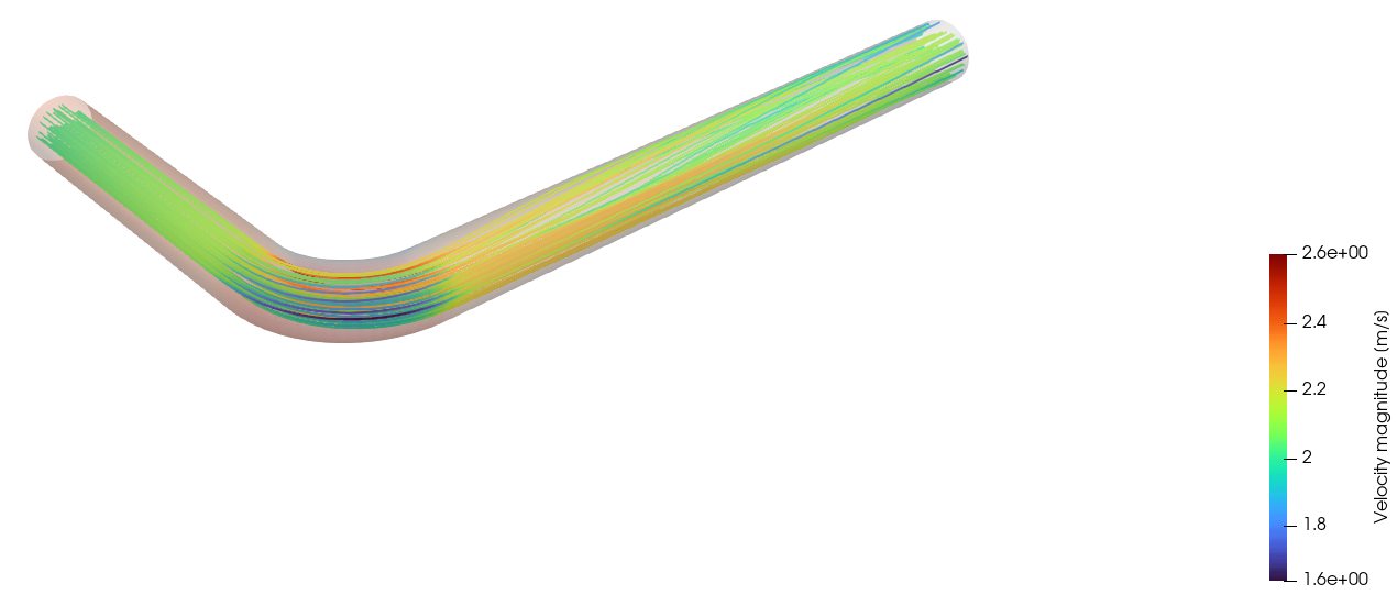
Streamlines through the pipe bend, coloured by velocity, inside the semi-transparent pipe wall.
Streamlines from the inlet, coloured by velocity.

Hot and cold water mixing in a tee

Cold water along a Ø50 mm main pipe meets hot water from a Ø32 mm branch. Each inlet brings its own temperature; Laminaro carries it with the flow and tells you how well the two streams have mixed by the outlet: the length a sensor or a thermostat needs downstream.

Set-up

Part
Ø50 mm main pipe (0.9 m), Ø32 mm branch from above, 0.3 m from the cold inlet
Flow
Cold water 15 °C at 1 m/s, hot water 60 °C at 1.5 m/s
Model
Temperature carried with the flow (mixing; the walls pass no heat)
Mesh
Standard, 531 k cells

Result

Outlet32.1 °C
Pressure drop1 160 Pa
Flow3.15 l/s
Checked against: the heat balance of the two streams: the flow-weighted mean of 15 °C and 60 °C over the two inlets' flows is the mixed temperature the outlet must reach, and the run's outlet sits on it.
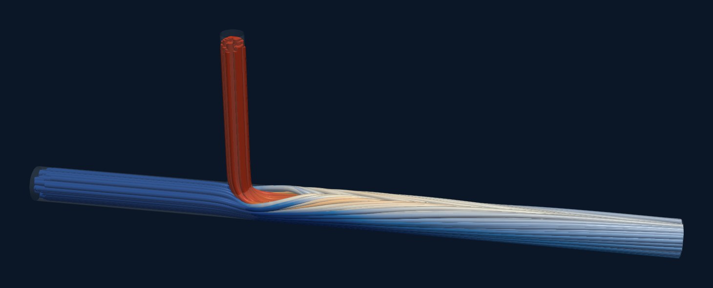
Streamlines through the mixing tee, coloured by temperature: the hot jet from the branch bends over with the cold stream and rides on top of it as a warm layer.
Streamlines coloured by temperature: blue 15 °C, red 60 °C. The hot jet rides on the cold stream before it mixes.

Diameter study

Which diameter gives the lowest pressure drop? The pipe's diameter D is an Inventor parameter; Laminaro runs one case per value and marks the best.

Set-up

Part
A 1 m pipe whose diameter D is a named Inventor parameter
Values
D = 60, 80 and 100 mm
Flow
Air at 20 °C, 5 m/s at the inlet
Mesh
Standard, about 493 k cells per case

Result

D 60 mm7.798 Pa
D 80 mm5.69 Pa
D 100 mm ✓4.479 Pa
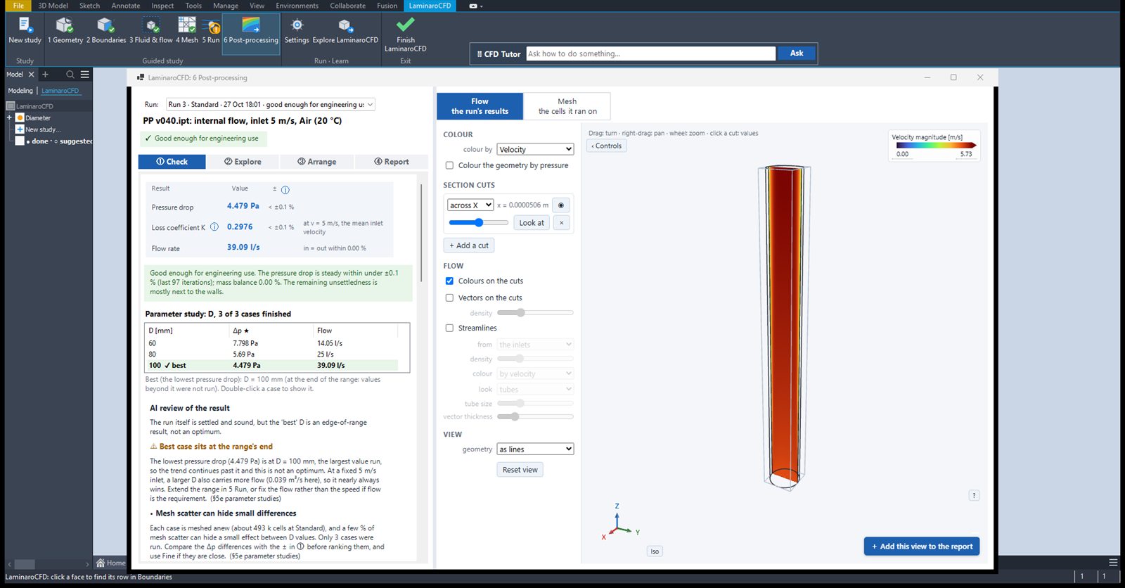
Checked against: the pipe-friction reference cases (Colebrook): −2.0 % at Re 10⁶ and −8.2 % at Re 10⁵. This study runs at lower Reynolds numbers still, so its ranking is more certain than its absolute pressure drops. The AI review says so too: the best case sits at the end of the range, so it is the best value tried, not an optimum.
The diameter study in Laminaro: a table of the three diameters with their pressure drops, D 100 mm marked best, and the AI review warning that the best case sits at the range's end.
Check: the three cases, the best one marked, and the AI review's note on the range.